Overview
This is a complete software-hardware project. The formal project scope is CONTROL02 for the remote controller and BOAT02 for the onboard receiver. The core goal was to build a wireless control system: the handheld side reads joystick input and sends a compact control packet, while the onboard side decodes that packet and drives steering and ESC throttle, forming a full chain from human input to boat actuation.
I entered the Sichuan University Water Star Model Boat Competition (Spring 2026) as its only one-person team. I independently completed all hardware-software design, fabrication, and full-system integration, advanced to the final, and placed 9th among 72 professional-division teams.
My role
- As the competition's only one-person team, independently completed the remote controller, onboard receiver, hardware-software design, PCB, soldering and fabrication, and full-system integration into a water-testable version.
- Independently implemented all code for the
CONTROL02remote andBOAT02onboard receiver, including ADC sampling, packet packing, NRF24L01 communication, PWM servo output, and ESC throttle control. - Designed a 3-byte control protocol: byte 1 stores steering angle, and bytes 2-3 store throttle. The receiver decodes the same format before driving the actuators.
- Independently completed hardware connection and debugging, including 3.3V power, filtering capacitors, crystal oscillator, nRF24L01 module, and external connectors.
- Added practical handling for joystick center jitter and safe ESC startup, including throttle dead zone, output limiting, LED self-test feedback, and ESC calibration.
Technical implementation
- The remote side uses STM32F103C8T6 and HAL to read two ADC channels on PA0 / PA1. One channel maps to a 0-180 degree steering angle, while the other is centered, dead-zoned, and mapped to a 0-1000 throttle value.
- The remote packs angle and throttle into
tx_data[3]and sends it through NRF24L01 over SPI1, using a 5-byte address, 2.402GHz channel, 1Mbps data rate, and automatic retransmission. - The onboard receiver enters NRF24L01 RX mode, reads the same 3-byte payload, sends angle to
Servo_SetAngle, and sends throttle toMotor_SetThrottle. - Steering uses TIM2 PWM, mapping 0-180 degrees to a 0.5ms-2.5ms pulse. Throttle uses TIM1 PWM, mapping 0-1000 throttle to a 1ms-2ms ESC pulse.
- On startup, the receiver centers the servo, runs NRF24L01 self-check, performs ESC calibration, and uses LED blink patterns for normal and fault states.
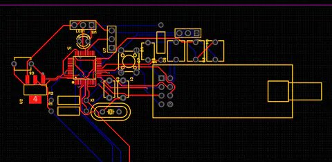
- The PCB was designed in JLC EDA and soldered by hand. The hardware side combines 3.3V regulation, parallel capacitors, and power filtering to reduce instability around the wireless module. The main engineering decision was to keep the protocol small. The remote does not send a complex structure; it sends only the interpreted steering angle and throttle. The receiver does not care about raw joystick values; it only decodes, limits, and outputs PWM. During water-side debugging, that made it possible to separate ADC jitter, wireless packet issues, ESC calibration, and servo response.
System Structure
- Input layer: the remote joystick outputs analog values, and STM32 samples ADC1 / ADC2 before converting them into steering and throttle commands.
- Communication layer:
nrf24l01.cwraps register read/write, send, receive, self-check, TX/RX mode switching, and FIFO clearing; both ends keep the same address and payload width. - Actuation layer: the onboard STM32 uses TIM2 for servo steering and TIM1 for ESC throttle, turning wireless data into physical movement.
- Protection and feedback layer: throttle dead zone reduces center jitter, output limiting keeps values in range, and LED feedback reports startup, self-check, fault, and throttle state.
- Hardware layer: the PCB connects power, the communication module, crystal, status LEDs, and external interfaces so the software control chain can run on the physical boat.
As a control flow, the system is a direct input-communication-output chain:
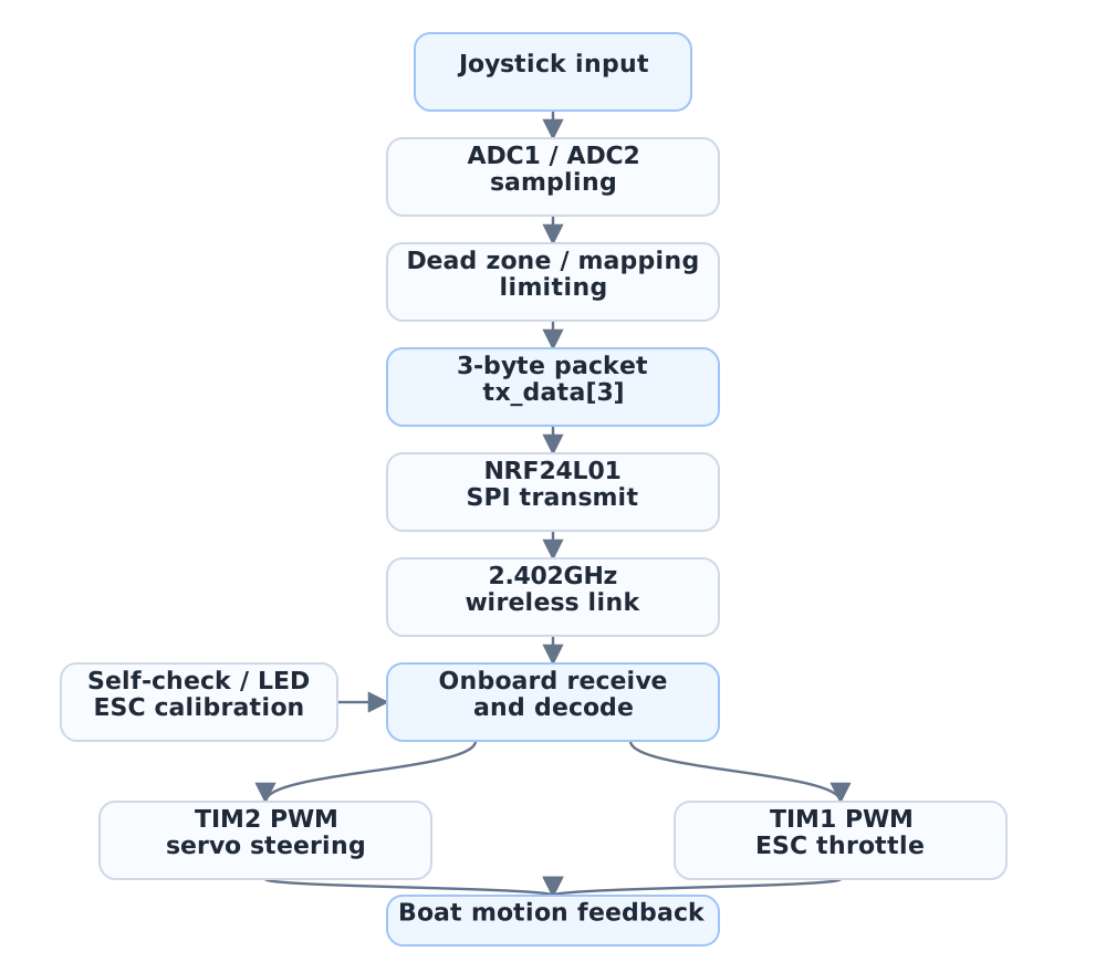
The protocol is intentionally small and explicit: the remote sends only steering angle and throttle, while the onboard receiver decodes, limits, and outputs PWM. That made debugging layered: first check ADC stability, then tx_data[3], then NRF24L01 packet reception, and finally actuator response.
As an engineering chain, the system is straightforward: joystick analog values enter ADC, are mapped into control values, compressed into a 3-byte packet, written to NRF24L01 over SPI, received on the boat, and converted into two 50Hz PWM outputs. Each layer has an observable checkpoint: ADC value, tx_data, NRF24L01 status, LED feedback, and actuator response.
Screenshots and Engineering Details
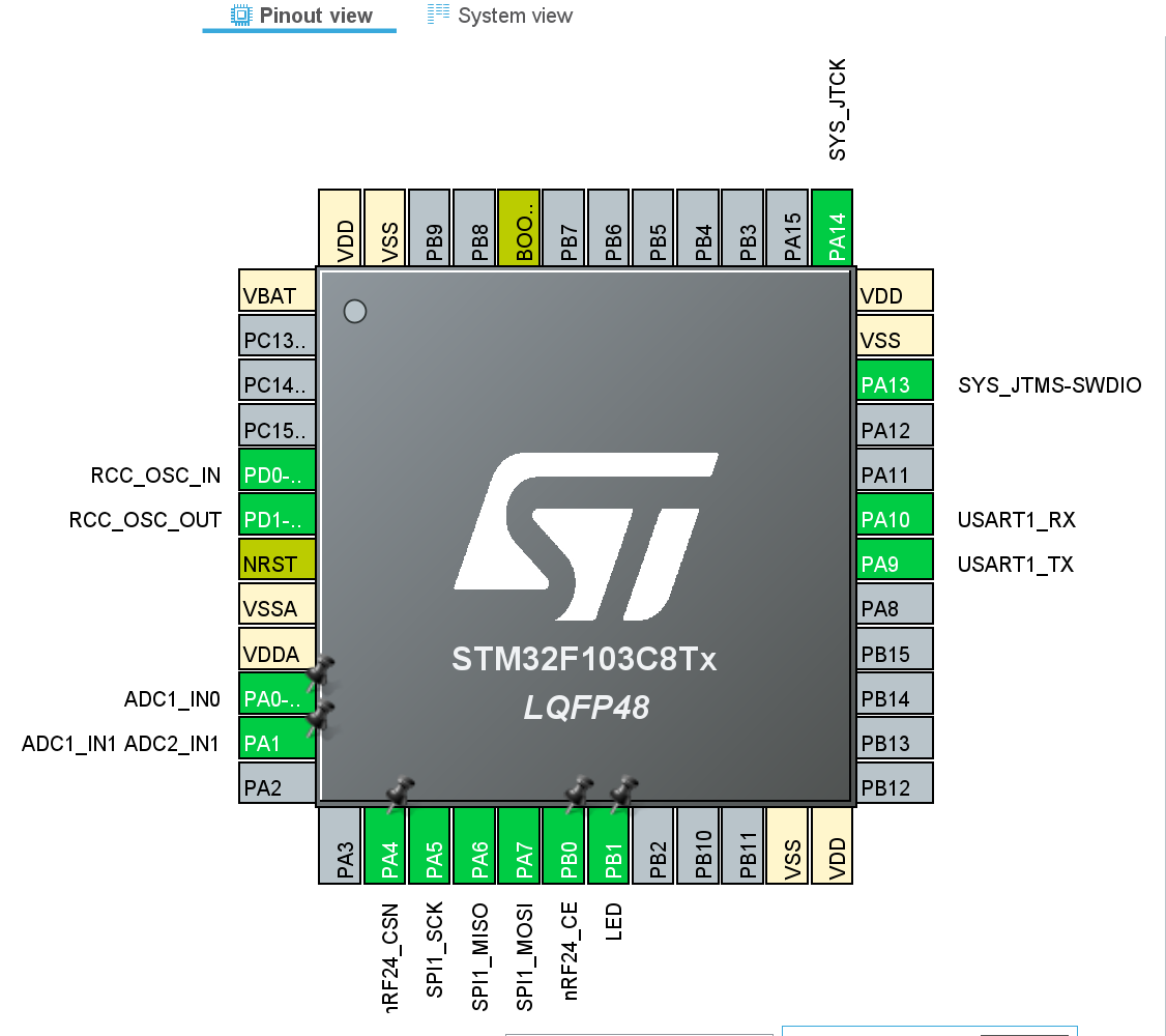
The pinout is built around the STM32F103C8T6, including ADC input, SPI communication, USART debugging, and basic GPIO output.
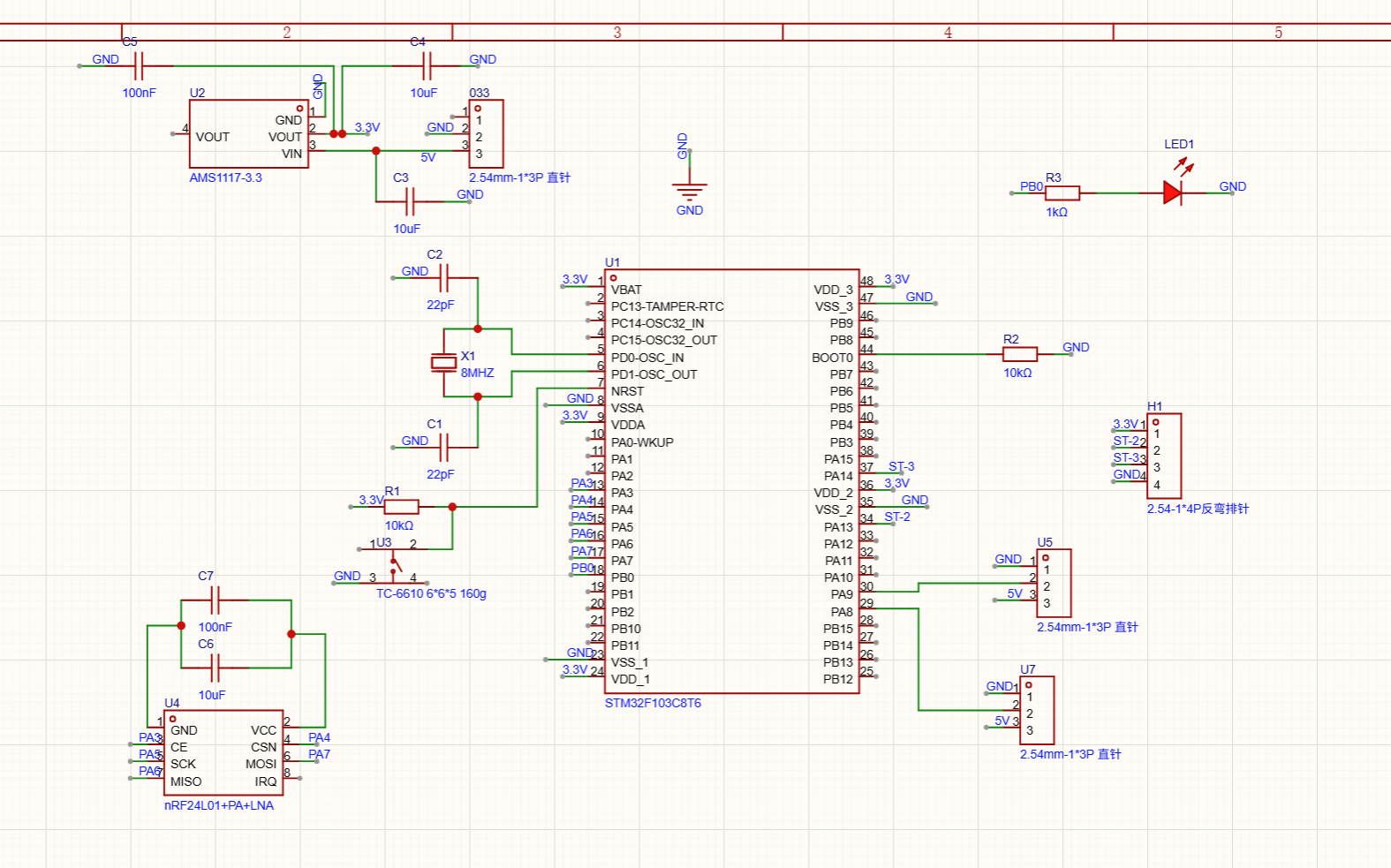
The schematic includes 3.3V regulation, power filtering, crystal oscillator, nRF24L01 communication module, status LED, and external connectors.
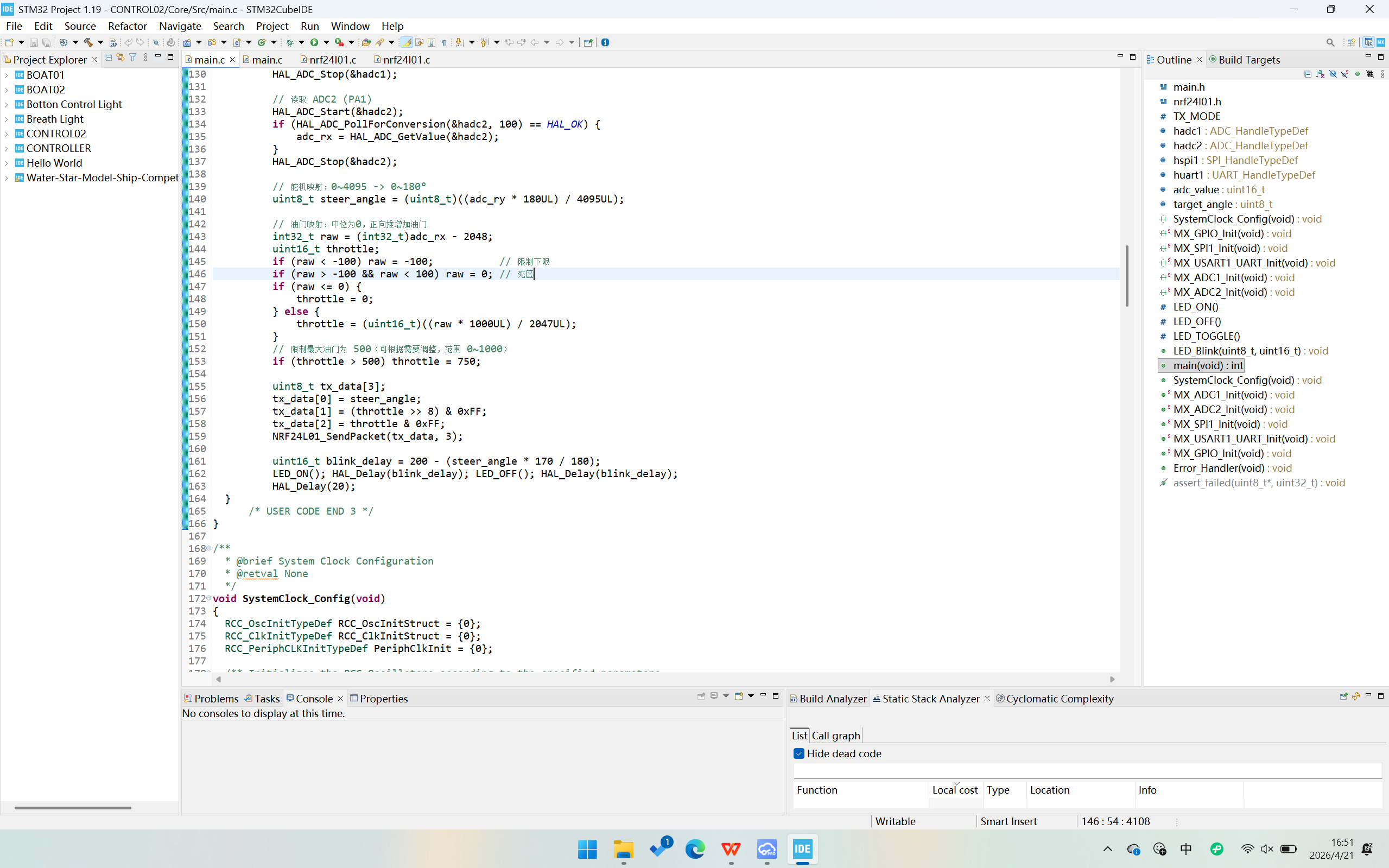
The code side handles ADC sampling, throttle and steering mapping, 3-byte packet transmission, nRF24L01 receive/decode, PWM output, and LED feedback, forming the control chain from remote input to onboard actuation.
Result
- Advanced to the final and placed 9th among 72 professional-division teams as the competition's only one-person team.